Monday October 27th, 2008...
Basic Initialization
hostname ASA1
interface GigabitEthernet0/0
nameif outside
security-level 0
ip address 1.1.1.1 255.255.255.0
logging console warnings
logging trap debugging
logging host inside 10.1.1.100
logging enable
Access Management
telnet 10.1.1.100 255.255.255.255 inside
ssh 10.1.1.0 255.255.255.0 outside
ssh timeout 5
Address Translation
access-list NONAT extended permit ip host 8.8.8.8 host 4.4.4.4
global (outside) 1 65.1.200.21-65.1.200.25 netmask 255.255.255.0
nat (inside) 0 access-list NONAT
nat (inside) 1 0.0.0.0 0.0.0.0
static (inside,outside) 65.1.15.251 10.1.1.251 netmask 255.255.255.255 (Access from outside to inside server)
static (outside,inside) 10.1.1.5 65.1.15.5 netmask 255.255.255.255 (Access from inside to outside server)
ACLs
Firewall transparent (transparent firewall mode)
access-list OUTSIDE extended permit eigrp host 150.100.3.4 any
access-list OUTSIDE extended permit icmp any any
access-list INSIDE extended permit tcp 150.100.3.0 255.255.255.0 any eq www
access-list INSIDE extended permit tcp 150.100.3.0 255.255.255.0 any eq https
access-list INSIDE extended permit tcp 150.100.3.0 255.255.255.0 any eq telnet
access-list INSIDE extended permit eigrp host 150.100.3.254 any
access-list INSIDE extended permit icmp any any
access-list INSIDE extended permit udp 150.100.3.0 255.255.255.0 any eq domain
access-group OUTSIDE in interface outside
access-group INSIDE in interface inside
IP Routing
route outside 0.0.0.0 0.0.0.0 192.1.12.2 1
route inside 10.3.3.0 255.255.255.0 10.2.2.5 1
router rip
network 65.0.0.0
network 192.168.6.0
passive-interface default
no passive-interface outside
no passive-interface inside
version 2
router ospf 1
network 65.1.15.101 255.255.255.255 area 2
router-id 11.11.11.11
log-adj-changes
default-information originate always
interface GigabitEthernet0/0
nameif outside
security-level 0
ip address 65.1.15.101 255.255.255.0
ospf message-digest-key 1 md5
ospf authentication message-digest
Object Groups
object-group protocol PROTOS
protocol-object gre
object-group icmp-type ICMP_ECHO
icmp-object echo
icmp-object echo-reply
object-group service MGMT_PORTS tcp
port-object eq telnet
port-object eq ssh
access-list OUTSIDE extended permit icmp any any object-group ICMP_ECHO
access-list OUTSIDE extended permit tcp any any object-group MGMT_PORTS
access-list OUTSIDE extended permit object-group PROTOS any any
!
access-group OUTSIDE in interface outside
VLANs
interface Ethernet0/0.55
vlan 55
nameif DMZ55
security-level 50
ip address 192.168.5.10 255.255.255.0 standby 192.168.5.11
!
interface Ethernet0/2
!
interface Ethernet0/2.10
description LAN Failover Interface
vlan 550
!
interface Ethernet0/2.20
description STATE Failover Interface
vlan 560
AAA
aaa-server TAC protocol tacacs+
aaa-server TAC host 10.1.1.100
key ipexpert
aaa authentication telnet console TAC
aaa authentication include telnet inside 0.0.0.0 0.0.0.0 0.0.0.0 0.0.0.0 TAC
aaa authentication include http inside 0.0.0.0 0.0.0.0 0.0.0.0 0.0.0.0 TAC
aaa authentication include telnet outside 0.0.0.0 0.0.0.0 0.0.0.0 0.0.0.0 TAC
aaa authentication include tcp/4515 inside 0.0.0.0 0.0.0.0 0.0.0.0 0.0.0.0 TAC
aaa-server RAD protocol radius
aaa-server RAD (dmz) host 10.1.200.251
key cisco
aaa authentication telnet console RAD LOCAL
aaa accounting telnet console RAD
telnet 10.1.33.3 255.255.255.255 inside
VPNs
crypto ipsec transform-set MYTRANS esp-3des esp-sha-hmac
crypto map MYMAP 10 match address L2L
crypto map MYMAP 10 set connection-type answer-only
crypto map MYMAP 10 set peer 192.1.12.15
crypto map MYMAP 10 set transform-set MYTRANS
crypto map MYMAP interface outside
crypto isakmp enable outside
crypto isakmp policy 10
authentication pre-share
encryption 3des
hash md5
group 2
lifetime 86400
crypto isakmp policy 65535
authentication pre-share
encryption 3des
hash sha
group 2
lifetime 86400
tunnel-group 192.1.12.15 type ipsec-l2l
tunnel-group 192.1.12.15 ipsec-attributes
pre-shared-key *
access-list L2L extended permit ip host 192.1.49.55 10.1.1.0 255.255.255.0
EZVPN
group-policy EZGroup internal
group-policy EZGroup attributes
wins-server value 10.2.2.175
dns-server value 10.2.2.175
vpn-idle-timeout 30
default-domain value ipexpert.net
username cisco password 3USUcOPFUiMCO4Jk encrypted
crypto ipsec transform-set MYTRANSFORM esp-des esp-md5-hmac
crypto dynamic-map MYDYN 5 set transform-set MYTRANSFORM
crypto map MYMAP 50 ipsec-isakmp dynamic MYDYN
crypto map MYMAP interface outside
crypto isakmp enable outside
crypto isakmp policy 10
authentication pre-share
encryption 3des
hash md5
group 2
lifetime 86400
crypto isakmp policy 65535
authentication pre-share
encryption 3des
hash sha
group 2
lifetime 86400
tunnel-group EZGroup type ipsec-ra
tunnel-group EZGroup general-attributes
address-pool MYpool
default-group-policy EZGroup
tunnel-group EZGroup ipsec-attributes
pre-shared-key *
WebVPN
http server enable
http redirect outside 80
webvpn
enable outside
username lab2 password cisco encrypted
Filtering
filter java 80 10.1.11.0 255.255.255.0 10.1.5.0 255.255.255.0
filter java 8080 10.1.11.0 255.255.255.0 10.1.5.0 255.255.255.0
filter activex 80 10.1.11.0 255.255.255.0 10.1.5.0 255.255.255.0
filter activex 8080 10.1.11.0 255.255.255.0 10.1.5.0 255.255.255.0
Failover
Active/Standby
ASA1
interface GigabitEthernet0/0
nameif outside
security-level 0
ip address 65.1.15.101 255.255.255.0 standby 65.1.15.102
no shut
!
interface GigabitEthernet0/1
nameif inside
security-level 100
ip address 150.100.1.101 255.255.255.0 standby 150.100.1.102
no shut
!
interface GigabitEthernet0/3
description STATE Failover Interface
no shut
!
interface Management0/0
description LAN Failover Interface
no shut
failover lan unit primary
failover lan interface FAILOVER_LAN Management0/0
failover key luan
failover replication http
failover link STATEFUL_LAN GigabitEthernet0/3
failover interface ip FAILOVER_LAN 1.1.1.1 255.255.255.252 standby 1.1.1.2
failover interface ip STATEFUL_LAN 1.1.1.5 255.255.255.252 standby 1.1.1.6
failover
ASA2:
failover
failover lan unit secondary
failover lan interface FAILOVER_LAN Management0/0
failover key luan
failover interface ip FAILOVER_LAN 1.1.1.1 255.255.255.252 standby 1.1.1.2
Layer 2 Transparent Firewall
firewall transparent
interface GigabitEthernet0/0.3
vlan 31
!
interface GigabitEthernet0/0.33
vlan 32
!
interface GigabitEthernet0/1
!
interface GigabitEthernet0/1.3
vlan 311
!
interface GigabitEthernet0/1.33
vlan 321
context custa
allocate-interface GigabitEthernet0/0.3
allocate-interface GigabitEthernet0/1.3
config-url disk0:/custa.cfg
!
context custb
allocate-interface GigabitEthernet0/0.33
allocate-interface GigabitEthernet0/1.33
config-url disk0:/custb.cfg
ip address 65.1.201.103 255.255.255.0 - Need IP address for L2 Transparent Firewall to work
Security Contexts (Virtual Firewall)
context custa
allocate-interface GigabitEthernet0/0
allocate-interface GigabitEthernet0/1
allocate-interface GigabitEthernet0/2
config-url disk0:/custa.cfg
!
context custb
allocate-interface GigabitEthernet0/0
allocate-interface GigabitEthernet0/1
allocate-interface GigabitEthernet0/3
config-url disk0:/custb.cfg
interface GigabitEthernet0/0
nameif outside
security-level 0
ip address 65.1.99.101 255.255.255.0
!
interface GigabitEthernet0/1
nameif dmz
security-level 50
ip address 10.1.1.101 255.255.255.0
!
interface GigabitEthernet0/2
nameif inside
security-level 100
ip address 10.1.101.101 255.255.255.0
custa-context
global (outside) 1 interface
global (dmz) 2 interface
nat (inside) 1 0.0.0.0 0.0.0.0
nat (outside) 2 access-list DMZ outside
static (dmz,outside) 65.1.99.253 10.1.1.253 netmask 255.255.255.255
static (dmz,outside) 65.1.99.251 10.1.1.251 netmask 255.255.255.255
access-list DMZ extended permit ip any host 65.1.99.253
access-list DMZ extended permit ip any host 65.1.99.251
route outside 0.0.0.0 0.0.0.0 65.1.99.6 1
access-list OUTSIDE extended permit icmp any any
access-list OUTSIDE extended permit tcp any host 65.1.99.253 eq www
access-list OUTSIDE extended permit udp any host 65.1.99.253 eq ntp
access-list OUTSIDE extended permit tcp any host 65.1.99.251 eq tacacs
access-list OUTSIDE extended permit udp any host 65.1.99.251 eq radius
access-list OUTSIDE extended permit udp any host 65.1.99.251 eq radius-acct
access-group OUTSIDE in interface outside
custb-context
access-list OUTSIDE extended permit icmp any any
access-list OUTSIDE extended deny ip any any log
access-list INSIDE extended permit tcp 10.1.101.0 255.255.255.0 host 6.6.6.6 eq www
access-list INSIDE extended permit icmp any any
access-group OUTSIDE in interface outside
access-group INSIDE in interface inside
global (outside) 1 interface
nat (inside) 1 0.0.0.0 0.0.0.0
route outside 0.0.0.0 0.0.0.0 65.1.99.6 1
Modular Policy Framework
class-map FTP
match port tcp eq ftp
class-map inspection_default
match default-inspection-traffic
class-map VOIP-SIG
match dscp af31
class-map VOIP-DATA
match dscp ef
policy-map VOIP-FTP
class VOIP-DATA
priority
class VOIP-SIG
priority
class FTP
police input 1000000 32000
service-policy VOIP-FTP interface outside
priority-queue outside
Application-Aware Inspection
High Availability Scenarios
QoS Policies
class-map class_ftp
match port tcp eq 2021
class-map inspection_default
match default-inspection-traffic
!
!
policy-map type inspect dns preset_dns_map
parameters
message-length maximum 512
policy-map global_policy
class inspection_default
inspect dns preset_dns_map
class class_ftp
inspect ftp
!
service-policy global_policy global
Other Advanced Features
arp outside 10.5.5.5 0012.8031.e118
arp inside 10.5.5.100 0003.6beb.1360
arp timeout 14400
MAC Aging
mac-address-table static outside 0012.8031.e118
mac-address-table static inside 0003.6beb.1360
ARP Spoofing
arp-inspection outside enable no-flood
arp-inspection inside enable no-flood
BGP passthrough
access-list OUTSIDE extended permit tcp host 10.1.11.1 host 10.1.11.254 eq bgp
static (inside,outside) 10.1.11.254 150.100.1.254 netmask 255.255.255.255
static (outside,inside) 150.100.1.1 10.1.11.1 netmask 255.255.255.255
access-group OUTSIDE in interface outside
Deny/Inspect SNMP
snmp-map NO_SNMP_V1
deny version 1
policy-map global_policy
inspect snmp NO_SNMP_V1
Monday, October 27, 2008
Friday, October 24, 2008
GET VPN
Cisco’s Group Encrypted Transport VPN (GET-VPN) is a tunnel-less VPN technology that leverages the existing core network and routing structure to interconnect nodes.
Tunnel definitions are not used, but rather an encryption policy based on access control lists is pushed down to each node from a central server. Data encryption is “on-demand” and is only applied to traffic that meets the specification of the access control lists.
Key Server
Tunnel definitions are not used, but rather an encryption policy based on access control lists is pushed down to each node from a central server. Data encryption is “on-demand” and is only applied to traffic that meets the specification of the access control lists.
Like tunnel-based VPNs, tunnel-less GET-VPN also encrypts the entire packet, but instead of generating a new header it recycles the original IP information. This “header preservation” takes advantage of the existing core routing structure for endpoint reachability, and eliminates the need for overlaid tunnels, preserves native Quality of Service support, and provides an efficient means for any-to-any (full-mesh) connectivity and for encrypted multicast replication.
GET VPN Components
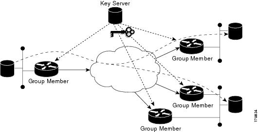
It is responsible for accepting or rejecting members into the VPN, generating/regenerating and distributing the encryption keys, and deploying the encryption policies to all of the registered Group Members.
A single Key Server is required, but multiple Key Servers can be deployed and is recommended to provide redundancy and load balancing since the encryption function of the VPN is dependent entirely upon the availability of the Key Server.
Group Member
Group Members are the individual node devices that protect local networks and encrypt traffic based on the encryption policy provided by the Key Server.
GDOI Group
The GET-VPN concept is based upon a “trusted group” model whose members employ a common security methodology. The GDOI group configuration, specified on the Key Server, contains the parameters needed to establish and maintain encryption policies between Group Members.
Identity
The identity number is a unique value that differentiates GDOI groups configured on a Key Server. No two groups can have the same identity number. The identity number determines which group the Group Member registers to.
Rekeying
In order to prevent service outages, GET-VPN initiates unicast rekeying events a minimum of 90 seconds prior to the expiration of the existing keys. The Key Server uses several parameters to attempt to estimate more accurately when to begin the rekeying process.
In addition to the TEK and KEK lifetime parameters, the Key Server uses the rekey retransmit number and time settings, and assumes a constant rekey processing time of 5 seconds per 50 Group Members.
With unicast rekeying, Group Members respond to rekey messages by replying to the Key Server with an acknowledgement.
If the Key Server does not receive acknowledgements for three consecutive rekey messages, it ejects that Group Member from the VPN, forcing it to reregister in order to resume sending encrypted traffic.
Multicast rekeying occurs 90 seconds prior to the SA expiration, and the rekey transmit time and rekey transmit number parameters are used to control how often and for how long the rekey messages will be transmitted. This is done to counter unexpected or intermittent packet loss, since Group Members do not acknowledge the receipt of multicast rekey messages.
Anti-Replay
Anti-replay mechanisms are used to prevent the retransmission of traffic captured in transit by a third party. GET-VPN can discard packets suspected of being replayed using either of two methods – counter-based and time-based.
Counter-based
Counter-based anti-replay uses a sliding window based on the sequence number of the arriving packets. If the sequence number of a packet is outside of the lower window boundary, it is considered to be a replayed packet and is discarded.
The use of counter-based anti-replay is common in tunnel-based VPNs, where there is a single pair of endpoints that packets travel between, providing a consistent parade of sequence numbers.
Time-based
Since counter-based anti-replay is of limited use in a tunnel-less environment, GET-VPN also offers anti-replay protection based on timestamp values using a mechanism called Synchronous Anti-Replay (SAR).
SAR is a GET-VPN-specific clocking function that is not dependent on the router’s time setting or on connectivity to an NTP source. The SAR clock runs continuously and tracks “pseudotime” in seconds, beginning with the successful registration of the first Group Member. The “authoritative” pseudotime is maintained by the Key Server and the current pseudotime value is periodically sent to the Group Members within a rekey message, effectively synchronizing the VPN.
The current pseudotime value is included with each encrypted packet that is created by a Group Member. When the packet arrives at the receiving Group Member, it compares the pseudotime value contained in the packet (the “pseudoTimeStamp”) with the running pseudotime value that it is maintaining. If the pseudoTimeStamp of the packet and the Group Member pseudotime are within the configured anti-replay window, then the packet is accepted.
CONFIGURATION
IKE Phase 1 Policy Commands using preshared key
crypto isakmp policy [IKE-Priority]
encryption [IKE-Encryption]
hash [IKE-Hash-Algorithm]
authentication pre-shared
group [IKE-DH-Group]
lifetime [IKE-SA-Lifetime]
crypto isakmp key 0 [KEY] address [GroupMember-IP-Address]
Key Server Configuration Commands
crypto key generate rsa label [NAME] modulus [MODULUS] (exportable)
crypto isakmp policy [IKE-Priority]
encryption [IKE-Encryption]
hash [IKE-Hash]
authentication pre-share
group [IKE-DH-Group]
lifetime [IKE-SA-Lifetime]
crypto isakmp key 0 [KEY] address [GroupMember]
crypto ipsec transform-set [NAME] [KEY] [HASH]
crypto ipsec profile [NAME]
set transform-set [NAME]
ip access-list extended [NAME]
permit [protocol] [source] [destination]
crypto gdoi group [NAME]
identity number [ID]
server local
rekey algorithm [TYPE]
rekey lifetime seconds [Lifetime]
rekey retransmit [TIME] number [NUMBER]
rekey authentication mypubkey rsa [RekeyNAME]
rekey transport unicast
registration interface [NAME]
address ipv4 [KeyServer]
sa ipsec [NUMBER]
profile [NAME]
match address ipv4 [NAME]
replay time window-size [SIZE]
Group Member Configuration Commands
crypto isakmp key 0 [Key] address [KeyServer]
crypto gdoi group [NAME]
identity number [Number]
server address ipv4 [KeyServer]
crypto map [NAME] [Sequence] gdoi
set group [NAME]
interface [WAN]
crypto map [NAME]
interface [WAN]
ip mtu 1480
Case Study

Key Server 1: Example
Key server 1 is the primary key server.
version 12.4
service timestamps debug datetime msec
service timestamps log datetime msec
no service password-encryption
service internal
hostname KS1
!
logging buffered 100000 debugging
no logging console
!
no aaa new-model
!
clock timezone EST 0
ip subnet-zero
no ip domain lookup
ip domain name cisco.com
!
crypto isakmp policy 1
encr 3des
authentication pre-share
group 2
lifetime 400
crypto isakmp key cisco address 10.1.1.13
crypto isakmp key cisco address 10.1.1.9
crypto isakmp key cisco address 10.1.1.1
crypto isakmp key cisco address 10.1.1.5
crypto isakmp key cisco address 10.1.1.21
!
crypto ipsec transform-set gdoi-trans-group1 esp-3des esp-sha-hmac
!
crypto ipsec profile gdoi-profile-group1
set security-association lifetime seconds 1800
set transform-set gdoi-trans-group1
!
crypto gdoi group group1
identity number 1
server local
rekey lifetime seconds 86400
rekey retransmit 10 number 2
rekey authentication mypubkey rsa group1-export-general
rekey transport unicast
sa ipsec 1
profile gdoi-profile-group1
match address ipv4 101
replay counter window-size 64
address ipv4 10.1.1.17
redundancy
local priority 10
peer address ipv4 10.1.1.2
!
interface Ethernet0/0
ip address 10.1.1.17 255.255.255.252
!
ip classless
ip route 0.0.0.0 0.0.0.0 10.1.1.18
!
access-list 101 permit ip 10.1.0.0 0.0.255.255 10.1.0.0 0.0.255.255
!
end
Key Server 2: Example
Key Server 2 is the secondary key server.
version 12.4
service timestamps debug datetime msec
service timestamps log datetime msec
no service password-encryption
service internal
!
hostname KS2
!
logging buffered 100000 debugging
no logging console
!
no aaa new-model
!
resource policy
!
clock timezone EST 0
ip subnet-zero
no ip domain lookup
ip domain name cisco
!
crypto isakmp policy 1
encr 3des
authentication pre-share
group 2
lifetime 400
crypto isakmp key cisco address 10.1.1.9
crypto isakmp key cisco address 10.1.1.1
crypto isakmp key cisco address 10.1.1.5
crypto isakmp key cisco address 10.1.1.17
crypto isakmp key cisco address 10.1.1.13
!
crypto ipsec transform-set gdoi-trans-group1 esp-3des esp-sha-hmac
!
crypto ipsec profile gdoi-profile-group1
set security-association lifetime seconds 1800
set transform-set gdoi-trans-group1
!
crypto gdoi group group1
identity number 1
server local
rekey lifetime seconds 86400
rekey retransmit 10 number 2
rekey authentication mypubkey rsa group1-export-general
rekey transport unicast
sa ipsec 1
profile gdoi-profile-group1
match address ipv4 101
replay counter window-size 64
address ipv4 10.1.1.21
redundancy
local priority 1
peer address ipv4 10.1.1.17
!
interface Ethernet0/0
ip address 10.1.1.21 255.255.255.252
!
ip classless
ip route 0.0.0.0 0.0.0.0 10.1.1.22
!
access-list 101 permit ip 10.1.0.0 0.0.255.255 10.1.0.0 0.0.255.255
!
end
Group Member 1: Example
Group Member 1 is part of a GDOI group that correlates with a VPN with which these sites are a part.
version 12.4
service timestamps debug datetime msec
service timestamps log datetime msec
no service password-encryption
!
hostname GM1
!
resource policy
!
clock timezone EST 0
ip subnet-zero
!
crypto isakmp policy 1
encr 3des
authentication pre-share
group 2
lifetime 3600
crypto isakmp key cisco address 10.1.1.17
crypto isakmp key cisco address 10.1.1.21
!
crypto gdoi group group1
identity number 1
server address ipv4 10.1.1.17
server address ipv4 10.1.1.21
!
crypto map map-group1 10 gdoi
set group group1
!
interface Ethernet0/0
ip address 10.1.1.1 255.255.255.252
crypto map map-group1
!
router bgp 1000
no synchronization
bgp log-neighbor-changes
network 10.1.1.0 mask 255.255.255.0
neighbor 10.1.1.2 remote-as 5000
no auto-summary
!
ip classless
!
End
Group Member 2: Example
Group Member 2 is part of a GDOI group that correlates with a VPN with which these sites are a part.
version 12.4
service timestamps debug datetime msec
service timestamps log datetime msec
!
hostname GM2
!
clock timezone EST 0
ip subnet-zero
!
crypto isakmp policy 1
encr 3des
authentication pre-share
group 2
lifetime 3600
crypto isakmp key cisco address 10.1.1.17
crypto isakmp key cisco address 10.1.1.21
!
crypto gdoi group group1
identity number 1
server address ipv4 10.1.1.17
server address ipv4 10.1.1.21
!
crypto map map-group1 10 gdoi
set group group1
!
interface Ethernet0/0
ip address 10.1.1.5 255.255.255.252
crypto map map-group1
!
router bgp 2000
no synchronization
bgp log-neighbor-changes
network 10.1.2.0 mask 255.255.255.0
neighbor 10.1.1.6 remote-as 5000
no auto-summary
!
ip classless
!
end
Group Member 3: Example
Group Member 3is part of a GDOI group that correlates with a VPN with which these sites are a part.
version 12.4
service timestamps debug datetime msec
service timestamps log datetime msec
no service password-encryption
!
hostname GM3
!
resource policy
!
clock timezone EST 0
ip subnet-zero
!
crypto isakmp policy 1
encr 3des
authentication pre-share
group 2
lifetime 3600
crypto isakmp key cisco address 10.1.1.17
crypto isakmp key cisco address 10.1.1.21
!
crypto ipsec transform-set gdoi-trans-group1 esp-3des esp-sha-hmac
crypto gdoi group group1
identity number 1
server address ipv4 10.1.1.17
server address ipv4 10.1.1.21
!
crypto map map-group1 10 gdoi
set group group1
!
interface Ethernet0/0
ip address 10.1.1.9 255.255.255.252
crypto map map-group1
!
router bgp 3000
no synchronization
bgp log-neighbor-changes
network 10.1.3.0 mask 255.255.255.0
neighbor 10.1.1.10 remote-as 5000
no auto-summary
!
ip classless
!
end
Group Member 4: Example
Group Member 4 is part of a GDOI group that correlates with a VPN with which these sites are a part.
version 12.4
service timestamps debug datetime msec
service timestamps log datetime msec
no service password-encryption
!
hostname GM4
!
clock timezone EST 0
ip subnet-zero
!
crypto isakmp policy 1
encr 3des
authentication pre-share
group 2
lifetime 3600
crypto isakmp key cisco address 10.1.1.17
crypto isakmp key cisco address 10.1.1.21
!
crypto gdoi group group1
identity number 1
server address ipv4 10.1.1.17
server address ipv4 10.1.1.21
!
crypto map map-group1 10 gdoi
set group group1
!
interface Ethernet0/0
ip address 10.1.1.13 255.255.255.252
crypto map map-group1
!
router bgp 4000
no synchronization
bgp log-neighbor-changes
network 10.1.4.0 mask 255.255.255.0
neighbor 10.1.1.14 remote-as 5000
no auto-summary
!
ip classless
!
end
For more Information on GET VPN:
DNS Exploit
Computer Academic Underground
Exploit Code
===============/========================================================
Exploit ID: CAU-EX-2008-0002
Release Date: 2008.07.23
Title: bailiwicked_host.rb
Description: Kaminsky DNS Cache Poisoning Flaw Exploit
Tested: BIND 9.4.1-9.4.2
Attributes: Remote, Poison, Resolver, Metasploit
Exploit URL: http://www.caughq.org/exploits/CAU-EX-2008-0002.txt
Author/Email: I)ruid
H D Moore
===============/========================================================
Description
===========
This exploit targets a fairly ubiquitous flaw in DNS implementations which allow the insertion of malicious DNS records into the cache of the target nameserver. This exploit caches a single malicious host entry into the target nameserver. By causing the target nameserver to query
for random hostnames at the target domain, the attacker can spoof a response to the target server including an answer for the query, an authority server record, and an additional record for that server, causing target nameserver to insert the additional record into the
Cisco's take on the exploit:
http://tools.cisco.com/security/center/viewAlert.x?alertId=16183
Defending using IPS DNS flood attack
DNS Application Inspection Configuration
DNS application inspection utilizes the Modular Policy Framework (MPF) for configuration. To configure application inspection, administrators may construct an inspection policy through the configuration of inspect class maps and inspect policy maps, which are applied via a global or an interface service policy. The following example demonstrates configuration of this feature.
!
class-map inspection_default
match default-inspection-traffic
!
policy-map type inspect dns preset_dns_map
parameters
!
!– Enable dns-guard to verify that DNS query and response transaction IDs match and only one ! DNS response is allowed through the firewall for each query.
!
dns-guard
!
!– Enable id-randomization to generate unpredictable DNS transaction IDs in !DNS messages and protect DNS servers and resolvers with poor randomization of !DNS transaction IDs.
!
id-randomization
!
!– Enable a maximum message length to help defeat DNS amplification attacks. Note: This is the ! default configuration and value based on RFC 1035.
!
message-length maximum 512
!
!– Enable id-mismatch to count DNS transaction ID mismatches within a specified period of time !and generate a syslog when the defined threshold has been reached.
!
id-mismatch count 10 duration 2 action log
exit
!
!– Check for DNS query messages with the recursion desired (RD) flag set in the DNS header !and drop those packets to avoid being used as a recursive resolver.
match header-flag RD
drop
!
policy-map global_policy
class inspection_default
inspect dns preset_dns_map
!
service-policy global_policy global
DNS Attack Identification
DNS Service Policy Identification
When the DNS guard, DNS ID randomization, DNS ID mismatch, and DNS protocol enforcement functions for the DNS application inspection feature are enabled, the show service-policy inspect command will identify the number of DNS packets inspected or dropped by these functions and this feature. Example output for show service-policy inspect dns follows
!– Output for service-policy applied globally
!
firewall# show service-policy inspect dns
Global policy:
Service-policy: global_policy
Class-map: inspection_default
Inspect: dns preset_dns_map, packet 37841, drop 0, reset-drop 0
message-length maximum 512, drop 0
dns-guard, count 21691
protocol-enforcement, drop 0
nat-rewrite, count 0
id-randomization, count 21856
id-mismatch count 10 duration 2, log 2
firewall#
!– Output for service-policy applied per interface
!
firewall# show service-policy inspect dns
Interface outside:
Service-policy: global_policy
Class-map: inspection_default
Inspect: dns preset_dns_map, packet 4923, drop 1544, reset-drop 0
message-length maximum 512, drop 39
dns-guard, count 2147
protocol-enforcement, drop 542
nat-rewrite, count 0
id-randomization, count 2220
id-mismatch count 10 duration 2, log 1
Interface inside:
Service-policy: global_policy
Class-map: inspection_default
Inspect: dns preset_dns_map, packet 240, drop 0, reset-drop 0
message-length maximum 512, drop 0
dns-guard, count 88
protocol-enforcement, drop 0
nat-rewrite, count 0
id-randomization, count 116
id-mismatch count 10 duration 2, log 0
firewall#
Syslog Identification
In the following example, the show logging | grep regex command extracts syslog messages from the logging buffer on the firewall. These messages provide additional information about denied packets. It is possible to use different regular expressions with the grep keyword to search for specific data in the logged messages.
Firewall syslog message 410002 will be generated when the firewall detects a high rate of DNS responses with a mismatched DNS transaction ID. The threshold for this function is set by the id-mismatch parameters submode command for policy-map type inspect dns. Additional information about this syslog message is available in Cisco Security Appliance System Log Message - 410002.
Firewall syslog message 106007 will be generated when the firewall detects that a DNS response message has already been received for a DNS query message and the connection entry has been torn down by the DNS guard function. This syslog message indicates that the DNS response message received has been denied. Additional information about this syslog message is available in Cisco Security Appliance System Log Message - 106007.
Additional information about regular expression syntax is available in Using the Command Line Interface.
  firewall#Ashow logging | grep (106007|410002)
  Mar 31 2008 00:29:18: %ASA-2-410002: Dropped 189 DNS responses with
    mis-matched id in the past 10 second(s): from outside:192.0.2.2/3917
    to inside:192.168.60.1/53
  Mar 31 2008 00:29:13: %ASA-2-106007: Deny inbound UDP from 192.0.2.2/2875
    to 192.168.60.1/53 due to DNS Response.
firewall# Monday, October 20, 2008
DMVPN with NHRP
In a dual cloud topology, two DMVPN networks are used to exchange traffic between devices. Two mGRE or two P2P-GRE interfaces are configured at each site not each device. Two tunnels are configured on a single CPE site and two tunnels are configured on a dual CPE site (one tunnel per CPE device). Dual Cloud Topologies can support the Hub and Spoke Deployment Model and the Spoke-to-Spoke Deployment Model. Multiple NHRP servers are required at the hub site (one for each cloud). Also, this helps to protect the customer’s hub from a single point failure.
Basic DMVPN Configuration
====================
! IKE Policy Configuration
!===================
! Creates the ISAKMP policy named “1″.
crypto isakmp policy 1
! Sets the encryption algorithm for protection suite.
encr aes 256
! Sets the hash algorithm for protection suite.
hash sha
! Sets the authentication method for protection suite.
authentication pre-share
! Set the Diffie-Hellman group.
group 5
! Set lifetime for ISAKMP security association
lifetime 86400
! Sets a wildcard pre-shared key for remote peers.
crypto isakmp key [PRESHARED_KEY] address 0.0.0.0
! Sets the keepalive interval for use with all peers. The Number of seconds
! between keep alives is set to 10. The number of seconds between retries
! is set to 4. The on-demand mode only sends DPD messages when needed.
crypto isakmp keepalive 10 4 on-demand
!===================
! IKE Policy Configuration
!===================
crypto isakmp policy 1
encr aes 256
hash sha
authentication pre-share
group 5
lifetime 86400
crypto isakmp key cisco address 0.0.0.0
crypto isakmp keepalive 10 4 on-demand
!=====================
! IPSEC Policy Configuration
!=====================
! Creates an IPSEC transform named “T1″ and defines the associated settings.
crypto ipsec transform-set T1 esp-aes 256 esp-sha-hmac
! Sets the IPSEC mode of opration to “transport” mode.
mode transport
! Creates an IPSEC policy profile named “P1″.
crypto ipsec profile P1
! Specifies the transform set to be used.
set transform-set T1
! Specifies the PFS Diffie-Hellman group.
set pfs group5
!====================
! IPSEC Policy Configuration
!====================
crypto ipsec transform-set T1 esp-aes 256 esp-sha-hmac
mode transport
crypto ipsec profile P1
set transform-set T1
set pfs group5
!================
! Hub - DMVPN Tunnel
!================
! Creates a tunnel interface.
interface Tunnel 0
! Defines the interface description.
description DMVPN Hub Primary Cloud
! Sets the bandwidth informational parameter.
bandwidth 10000
! Sets the IP address of the tunnel interface.
ip address [TUNNEL_IP] [TUNNEL_MASK]
! Sets the IP Maximum Transmission Unit.
ip mtu 1400
! Sets the NHRP authentication string.
ip nhrp authentication [NHRP_PRESHARED_KEY]
! Dynamically learn NBMA mapping for broadcasts/multicasts
ip nhrp map multicast dynamic
! Sets the NHRP NBMA network identifier.
ip nhrp network-id [NHRP_NETWORK_ID]
! Sets the NHRP advertised holdtime.
ip nhrp holdtime 600
! Specifies the interface throughput delay.
delay [TUNNEL_DELAY]
! Sets the source IP address of the tunnel packets.
tunnel source [PUBLIC_INTERFACE_INSTANCE]
! Enables Multipoint GRE mode.
tunnel mode gre multipoint
! Sets a tunnel security or selector key.
tunnel key [TUNNEL_KEY]
! Enables IPSEC tunnel protection.
tunnel protection ipsec profile P1
!=================
! Hub - DMVPN Tunnel
!=================
interface Tunnel 0
description DMVPN Hub Primary Cloud
bandwidth 10000
ip address 172.17.0.1 255.255.255.0
ip mtu 1400
ip nhrp authentication cisco
ip nhrp map multicast dynamic
ip nhrp network-id 1
ip nhrp holdtime 600
delay 100
tunnel source GigabitEthernet0/1
tunnel mode gre multipoint
tunnel key 1
tunnel protection ipsec profile P1
!===================
! Spoke - DMVPN Tunnel
!===================
! Creates a tunnel interface.
interface Tunnel [TUNNEL_INSTANCE]
! Defines the interface description.
description [TUNNEL_DESCRIPTION]
! Sets the bandwidth informational parameter.
bandwidth 10000
! Sets the IP address of the tunnel interface.
ip address [TUNNEL_IP] [TUNNEL_MASK]
! Sets the IP Maximum Transmission Unit.
ip mtu 1400
! Sets the NHRP authentication string.
ip nhrp authentication [NHRP_PRESHARED_KEY]
! Creates a static NHRP mapping for the hub router.
ip nhrp map [HUB_TUNNEL_IP] [HUB_PUBLIC_IP]
! NBMA mapping for broadcasts/multicasts. Used to dynamically learn
! destinations from client registrations on hub.
ip nhrp map multicast [HUB_PUBLIC_IP]
! Sets the NHRP NBMA network identifier.
ip nhrp network-id [NHRP_NETWORK_ID]
! Sets the NHRP advertised holdtime.
ip nhrp holdtime 600
! Sets the IP address of the NHRP server located at the hub.
ip nhrp nhs [HUB_TUNNEL_IP]
! Specifies the interface throughput delay.
delay [TUNNEL_DELAY]
! Sets the source IP address of the tunnel packets.
tunnel source [PUBLIC_INTERFACE_INSTANCE]
! Sets the destination IP address of the tunnel packets.
tunnel destination [HUB_PUBLIC_IP]
! Sets a tunnel security or selector key.
tunnel key [TUNNEL_KEY]
! Enables IPSEC tunnel protection.
tunnel protection ipsec profile P1
!===================
! Spoke - DMVPN Tunnel
!===================
interface Tunnel 0
description DMVPN Spoke Primary Cloud
bandwidth 10000
ip address 172.17.0.2 255.255.255.0
ip mtu 1400
ip nhrp authentication cisco
ip nhrp map 172.17.0.1 10.0.0.1
ip nhrp map multicast 10.0.0.1
ip nhrp network-id 1
ip nhrp holdtime 600
ip nhrp nhs 172.17.0.1
delay 100
tunnel source FastEthernet0
tunnel destination 10.0.0.1
tunnel key 1
tunnel protection ipsec profile P1
Next-Hop Resolution Protocol (NHRP)
When traffic is exchanged between two devices in a DMVPN network, the devices must learn where the GRE interface for the other device publicly resides in the NBMA network. This information is learnt through the Next-Hop Resolution Protocol (NHRP). When a device on the Spoke’s private network initiates a session to a device on the Hub’s private network, a routing table lookup is executed and determines the destination network is reachable through IP address 10.0.0.1 via interface Tunnel 0. The session traffic is then forwarded out the Tunnel0 interface where an NHRP lookup is executed. The map entry in the Spoke NHRP Table indicates the Hub GRE (End-Point) is located at NBMA IP address 10.0.0.1. From this information, the session traffic is forwarded out a dynamic GRE/IPSEC tunnel to the hub as demonstrated in the diagram. The Hub receives the session traffic and forwards it to the destination device.
NHRP Registration Order of Operation
A static NHRP mapping is configured for the NHRP server configured at the Hub which forces the spoke to initiate an NHRP Registration Request to the Hub. The NHRP Registration Request causes an IKE session to be initiated with the Hub. Once the IKE/IPSEC sessions are established, the NHRP Registration request is forward over the IPSEC/GRE tunnel.
The Hub processes the NHRP Registration Request received from Spoke1, creates an entry in the NHRP table and sends an NHRP Registration Reply to Spoke1 indicating the spoke was successfully registered.
Data exchanged between the hub and spokes are sent over the IPSEC/GRE tunnel.
Subscribe to:
Posts (Atom)